Initial vs. Final Designs
The Beam Reaction model started out with all parts, except the scales, made from wood, and the support edges were rounded to improve their durability. The initial design had no means to apply moment, the beam width was too narrow, and the supports were found to “wander” during the course of the experiments.
The final version of the beam kit, with etched ruler and logo, 3D printed supports, laser etched weights, torque tool, matchsticks, and weigh scales is shown on the right below, while the corresponding original components are shown on the left.
| Initial Design | Final Design | |
|---|---|---|
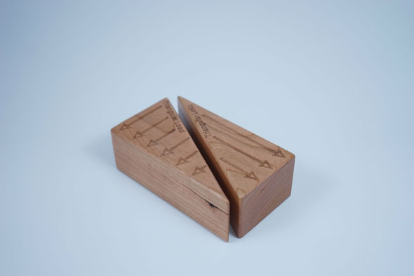
| Beams | 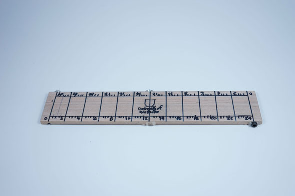 |
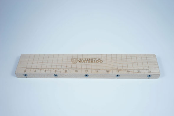 |
| Rectangular Blocks | 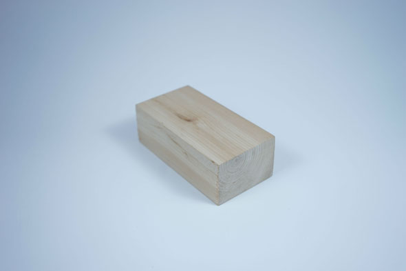 |
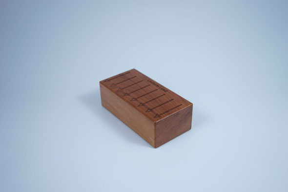 |
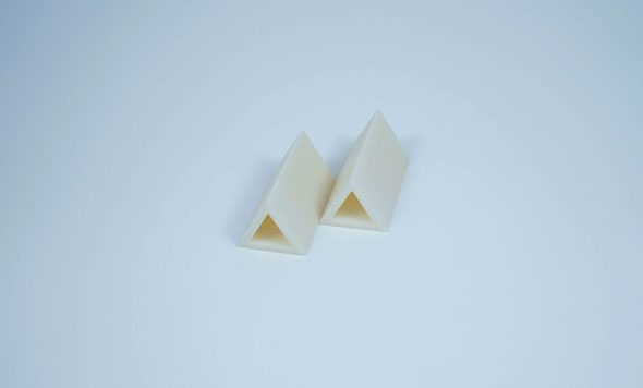
| Triangular Blocks | 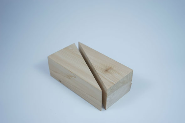 |
 |
| Supports | 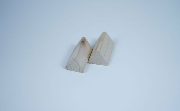 |
 |
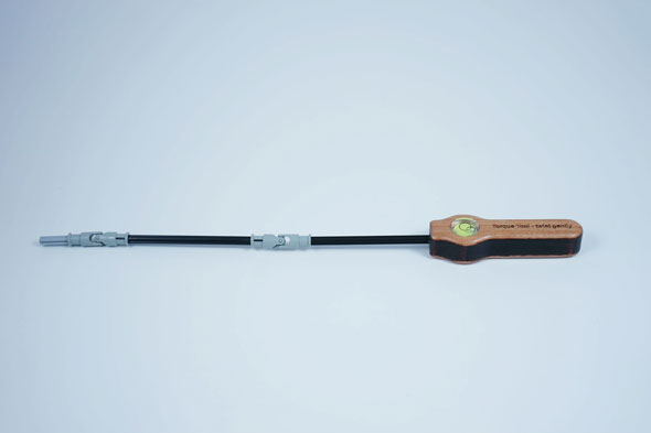
| Torque Tool | 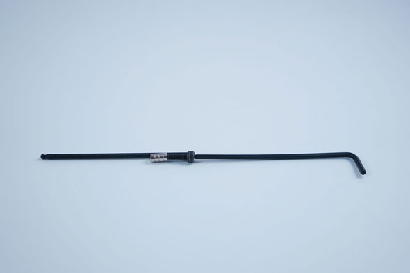 |
 |
| Matchsticks | 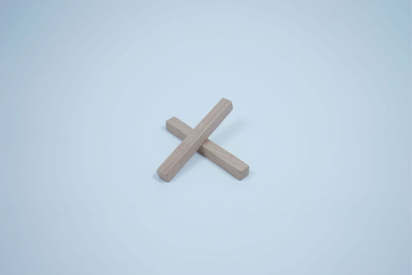 |
|
| Weigh Scale | 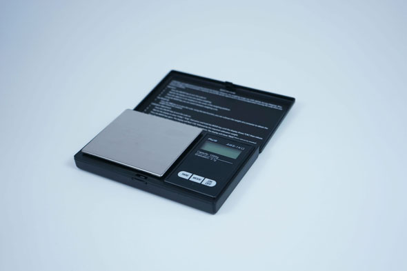 |
We wanted the torque application to be screwdriver-like, something that students would readily associate with torque. Initially, we tried using a Robertson screw and screwdriver or an Allen screw and key (see photo above). In both cases, unintentional vertical loads applied by the operator during torque application rendered the scale readings unusable, and large horizontal forces were needed to keep the driver properly engaged with the screw head. Rare-earth magnets improved driver engagement, but did little to eliminate the spurious vertical forces. We then tried several designs that included 2 U-joints so that vertical loads could not be transferred to the beam.
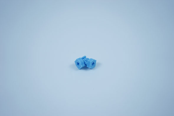
Eventually, plastic Lego U-joints, shafts and shaft couplings (embedded into the side of the beam) were tried and they worked very well. Unfortunately these parts are no longer manufactured, and we used all of the stock we could find for our 40 units. In future, we recommend 3D printed U-joints – like those kindly manufactured by my friend Steve Leis and his son Peter (see photo below) – but with integrated shafts. 3D printed shafts might be given a plus-sign cross-section as doing so offers good strength, good torsion at joints and low torsional stiffness (see below). Inserts with matching sockets could then be used on the sides of the beams. The shafts were bonded into the handles using high-temperature hot glue, while the bubble levels and beam inserts were bonded using moderate-temperature hot glue. The epoxy and other chemically-activated glues we tried did not provide adequate bonding.
The next problem we faced was finding a way to apply a consistent amount of torque. Torque sensing screwdrivers are available commercially, but they range in price from several hundred to more than a thousand dollars. We considered 3D printing a custom screwdriver-like torque tool, but we felt that the development time would be too long.
In the end, we decided to take advantage of the torsional flexibility of the Lego shafts, and we offset the torque tool handle and accompanying bubble level by 45 degrees from the plus-sign shape of the axle. Students then applied whatever torque was required to twist the three end-to-end axle pieces a total of 45 degrees. This was found to be highly repeatable, easy to describe through written instructions and straightforward for students to grasp conceptually.
See Downloadables