Description
Shear in beams is one of the most challenging concepts for young students of mechanics to grasp. The derivation involves visualization of bending stresses, cutting planes, force balances, and more visualizations. A suitable physical model (Figs 1-3) can do much of the heavy lifting and thereby free students to concentrate on force balances rather than the mental gymnastics of visualization. This model was originally inspired by a photo in Mechanics of Materials (1976), a textbook by E.P. Popov, a figure that I found very helpful.
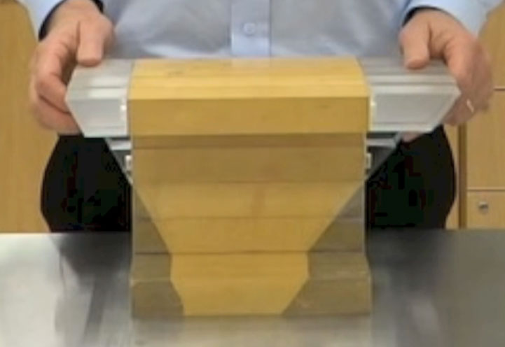 Figure 1 – Side View of Model
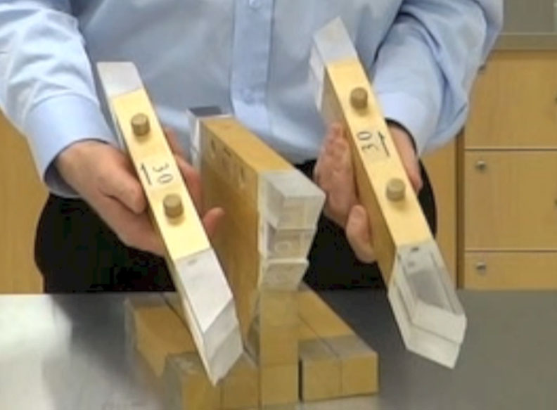 Figure 2 – Shear Forces on the Flanges
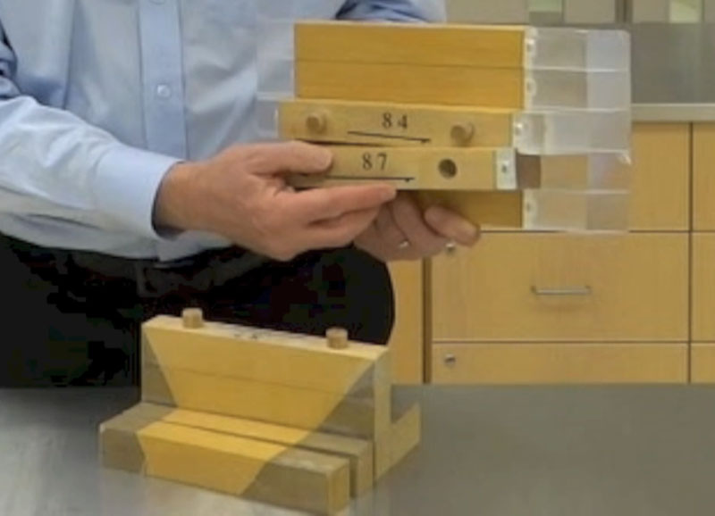 Figure 3 – Shear Forces Near the Neutral Axis of the Beam
In order to provide a real-world context for shear flow, the model can be considered to be part of a worked cantilever beam problem (Fig. 4), the details of which can be found here.
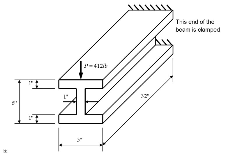 Figure 4 – The Model as Part of a Cantilever Beam
Learning Objectives
The model helps students to:
- Visualize bending stresses and how they vary from place to place along the length of a beam
- Understand how individual fibers experience axial imbalances as a result of these varying stresses
- Envision how shear stresses must act in order to keep defined groups of fibers firmly attached to the rest of the beam
- Grasp why shear loads increase as more fibers in a contiguous group on one side of the neutral axis (NA) are envisioned as cut away from the rest of the beam,
- Comprehend why shear force decreases when fibers from the other side of the NA are added to the excised group
- Explain why the maximum shear stress occurs at the NA of the beam
- Understand how these axial shear loads give rise to shear flow on a cross-section of a beam
- Correctly predict the angular direction of the shear flow at any location on the cross-section of a simple prismatic beam
- Know how to choose the proper thickness, b, for calculating shear stress (many textbooks get this wrong!).
Model Construction
The model is easy to build, and we recommend using Maple or some other durable hardwood. Sizing of the blocks will depend on the desired size of the assembled model. For a model approximately the size of ours, we suggest that boards be cut and planed into 3.5 cm x 3.5 cm sticks and then cut to 20cm lengths. Fourteen (14) such wood blocks are required. In addition, 14 Plexiglas prisms are needed to represent the tension stresses. Compressive stresses can be represented as overlays on the wooden parts of the model using wood stain, paint, or self-adhesive film.
Additional Information
See the Downloadables section for more information on this activity.