Student Handout
For ideas on how students can use the “Forces on Submerged Surfaces” model, please view this video.
General Activity Contract


Spreadsheet

For ideas on how students can use the “Forces on Submerged Surfaces” model, please view this video.
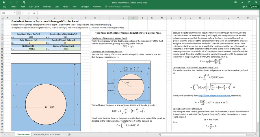
This spreadsheet allows students to calculate the total hydrostatic force on submerged triangular, rectangular and circular surfaces, and the center of pressure locations for each. For usage instructions please see this video.
Unfortunately, detailed drawings are not available for the “Forces on Submerged Surfaces” model (Fig. 1). The original design was described in drawings of various formats, significant enhancements were made as the engineering machine shop translated those sketches into CNC files, and the final files were lost due to a personnel change.
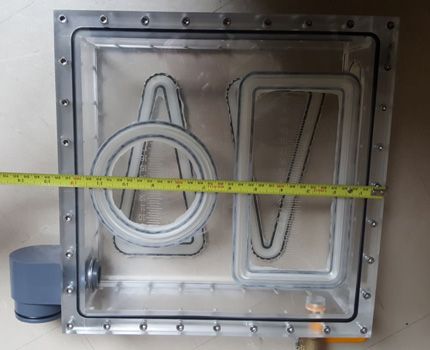
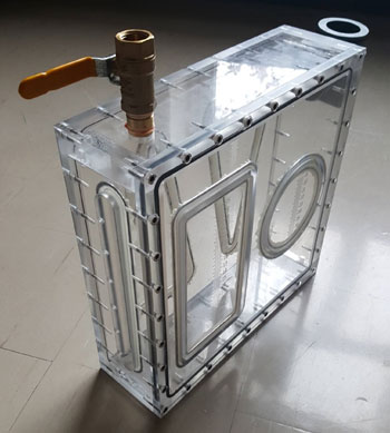 Fig. 1 – The Hydrostatic Pressure Apparatus
To aid others in replicating the model, we have provided a series of photos and sketches that capture the main features of the apparatus, and we have provided suggestions for further improvements.
As shown in Fig. 1 and this video, the pressure box consists of a closed chamber with a pressure tube attached to one of its vertical sides and a drain valve on the top of the chamber near its other end. Moveable rectangular and circular panels are attached by thin rubber membranes to one of the windows that forms a large face of the box, and the other large face contains two triangular panels. A long narrow membrane on the vertical side near the drain valve allows students to “feel” the hydrostatic pressure at various elevations.
The core of the pressure box is a square Plexiglas frame made by solvent welding four flat pieces together as shown in Fig. 2. Windows are attached on each of its large faces using 32, 6mm Allen-head screws, and O-rings on each side of the frame provide waterproof sealing between the frame and the windows
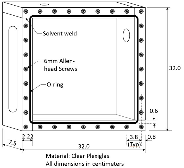 Figure 2 – Core Frame
One of the windows (Fig. 3) has two 10cm-wide by 40cm-tall triangular panels and the other has a 10cm-wide by 40cm-tall rectangular panel and a 10cm-diameter circular panel (Fig. 4).
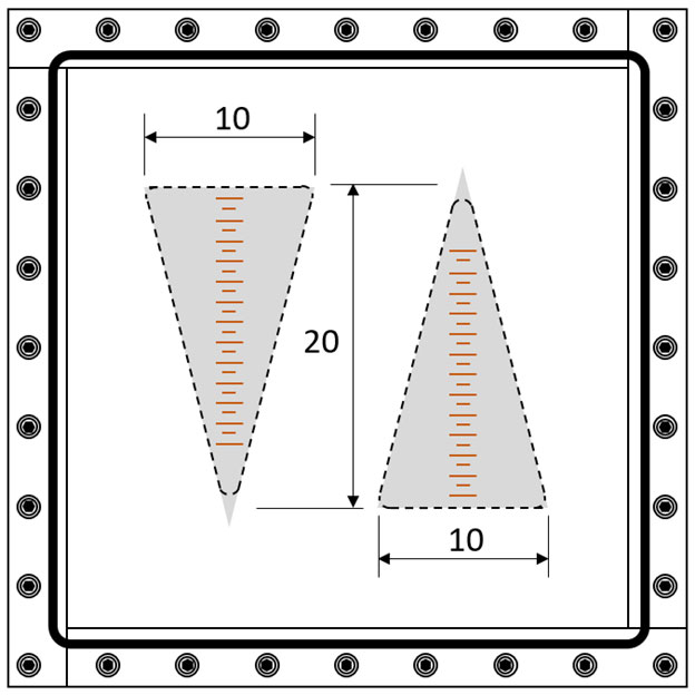 Figure 3 – Window with Triangular Panels
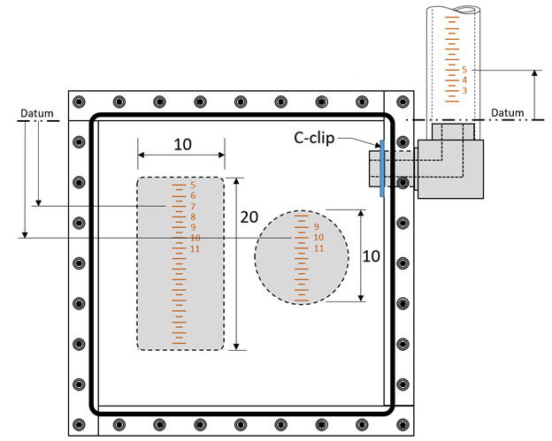 Figure 4 – Window with Rectangular and Circular Panels
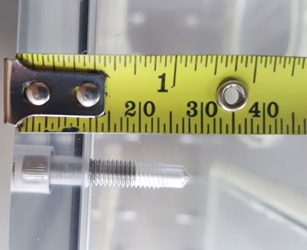
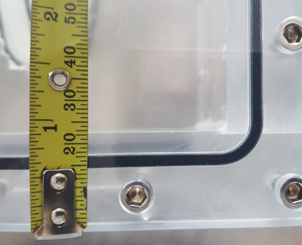
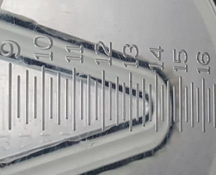
All of the engraved depth indicators (used for calculating the water depth above the top of any particular panel and for measuring the COP location) should be registered to a common datum, such as the underside of the top of the frame, as indicated in Fig. 4. The “ticks” on the depth indicator are sufficiently wide and deep that the chisel point on the force gauge (Fig. 5) can rest in them without sliding. This feature is very useful when students are trying to find the panel center of pressure.
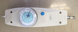 Figure 5 – Force Gauge (photo by Tina Wu)
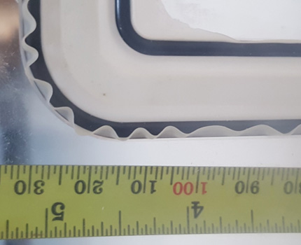
The panels are attached to the windows by flexible rubber membranes (Fig. 6), so that they can move in and out of the plane of the windows. A small gap exists along the perimeter of each panel (not visible in Fig. 6, but shown in Fig. 7) and the window that supports it. When the pressure box is filled with water, the panels move outwards (see video) until the membranes stretch sufficiently that they carry the forces produced by the hydrostatic pressure on the panel (plus approximately half of the forces on the membrane as it spans the gap between the panel and window). That is why the nominal panel dimensions (as used in the spreadsheet) are to the center of the gap (Fig. 7).
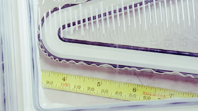 Figure 6 – Membrane Detail
When any given panel is pushed back flush with the window using the force gauge, the membrane exerts no force on it. The location where the force gauge must be applied is the “point of balance” for the applied force, that is the center of pressure, and, the force measured is that produced by the water pressure acting on the panel.
The membranes are attached to the panel and its surrounding window by O-rings that sit in T-slots (Fig. 7). The O-rings must sit tight in the slots in order for the pinch points to prevent water leakage. The panel dimensions shown in Figs 3 and 4 are measured to the center of the gap.
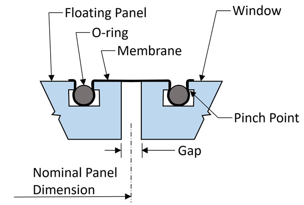 Figure 7 – Cross-section of Membrane System
The membrane in the long slot of the core frame (used to obtain a manual indication of pressure at various depths) is supported around its edges by an O-ring and T-slot.
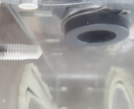
Lastly, the pressure tube is attached to the pressure box by an elbow fitting that has an O-ring over which the graduated pressure tube can be placed (see Fig. 4). An internal O-ring (Fig. 9) allows a smaller-diameter pressure tube to also be used (to demonstrate that tube diameter does not affect the pressures and forces produced).
Notice the “shoulder” between the body of the elbow and the Plexiglas box. It allows the elbow to rotate more easily and avoids scratching of the box. Additional dimensions of the elbow can to obtained from Fig. 10.
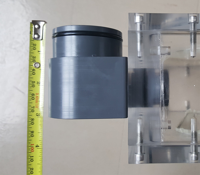 Figure 8 – Elbow Side View
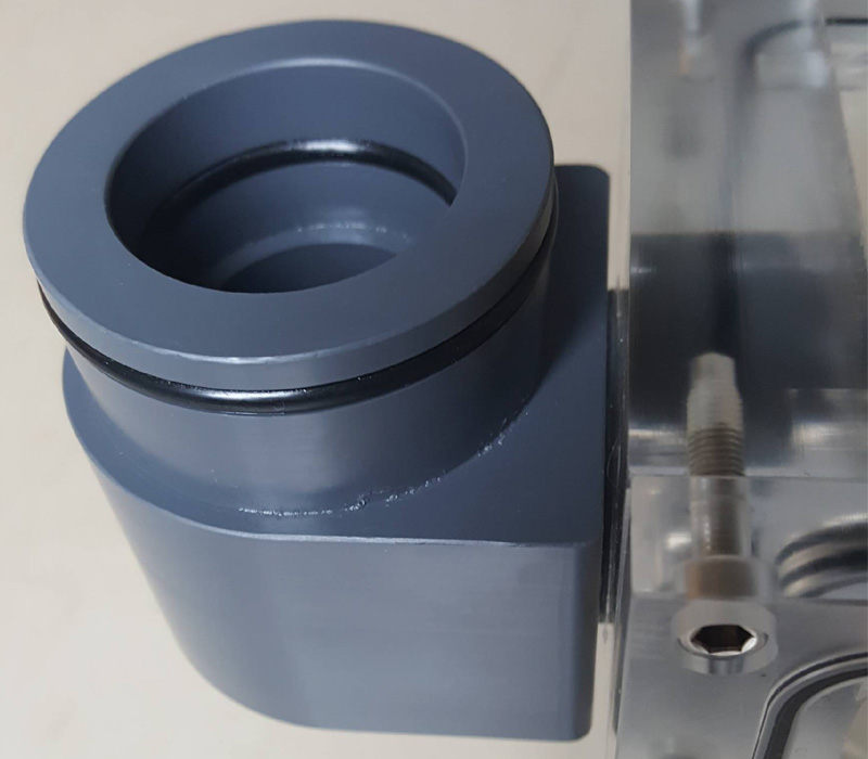 Figure 9 – Elbow Detail
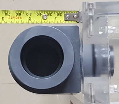 Figure 10 – Elbow End View
The elbow rotates where it enters the pressure box and is held in place by a C-clip (Fig. 4). Rotation of the elbow allows the box to be stored easily with the pressure tube attached. It also allows the pressure box to be placed on its side so that the panels are horizontal. (Fig. 11)
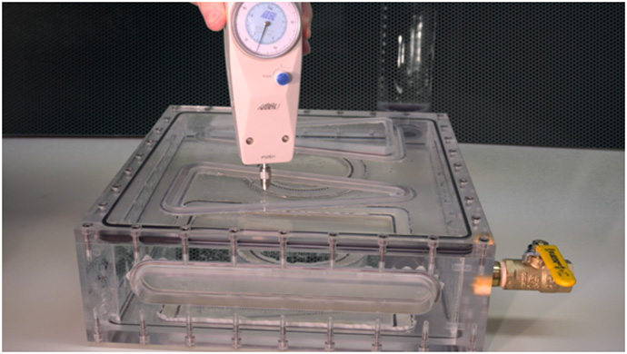 Figure 11 – Using the Pressure Box on its Side
The drain valve facilitates filling and draining of the pressure box. Both should be slightly recessed on the inside of the box, and we would do so if we were building additional sets of the apparatus. We recommend using de-ionized water so as to prevent residue inside the box when any undrained water dries.
Below, are a few additional images of the pressure box.