
Modern day infrastructure inspection is commonly done using human visual inspections. Human inspectors have a difficult time detecting and measuring quantity or size
of defects on a large scale. This problem is often atttributed to lack of large scale measurement tools that can be used to quantify objects of interest rapidly.
Other problems with manual inspection include:
This research work aims to use mobile robotics to help suppliment or replace human visual inspection of infrastructure. We primarily focus on inspection of the following types of infrastructure:
Three prototype inspection robots have been developed for the purpose of infrastructure inspection research. All sensors are time synchronized and calibrated intrinsically for internal parameter estimation, and extrinsically for estimates of the physical transformation between each sensor frame.
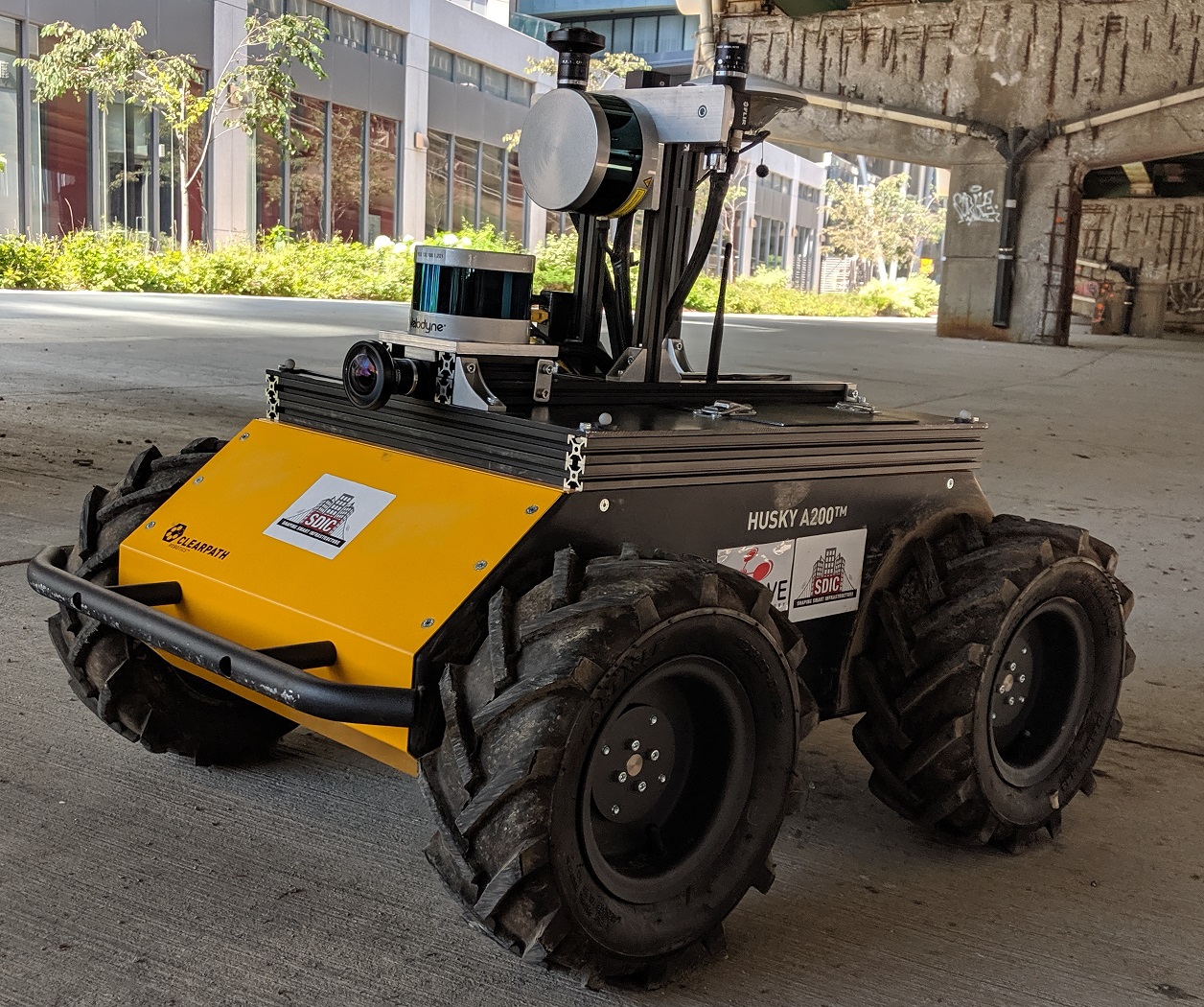
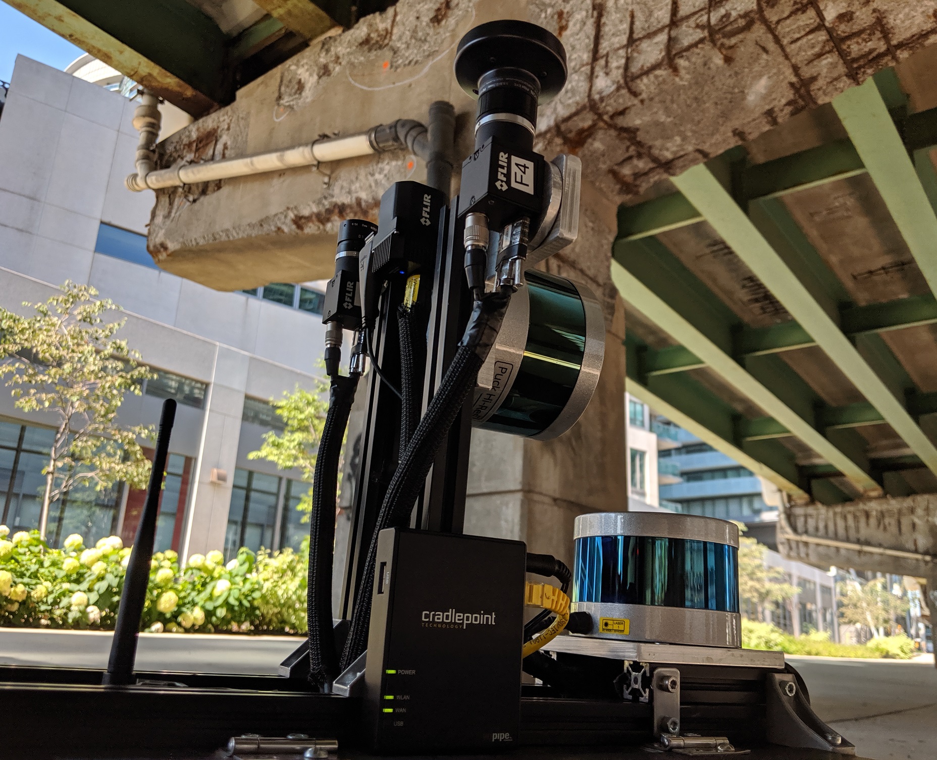
Figure 3 and 4: Husky based inspection UGV with sensors including (A) Vertical Lidar (VLP-16 HiRes) (B) Horizontal Lidar (VLP-16 Lite) (C) Swift Nav Piksi-Multi RTK GPS (D) 3 Flir BlackflyS machine vision cameras with narrow FOV and Fisheye lenses (E) Flir ADK Infrared Spectrum Camera (F) Inertial Measurement Unit (UM7) (G) Custom PCBs for data i/o and hardware triggering
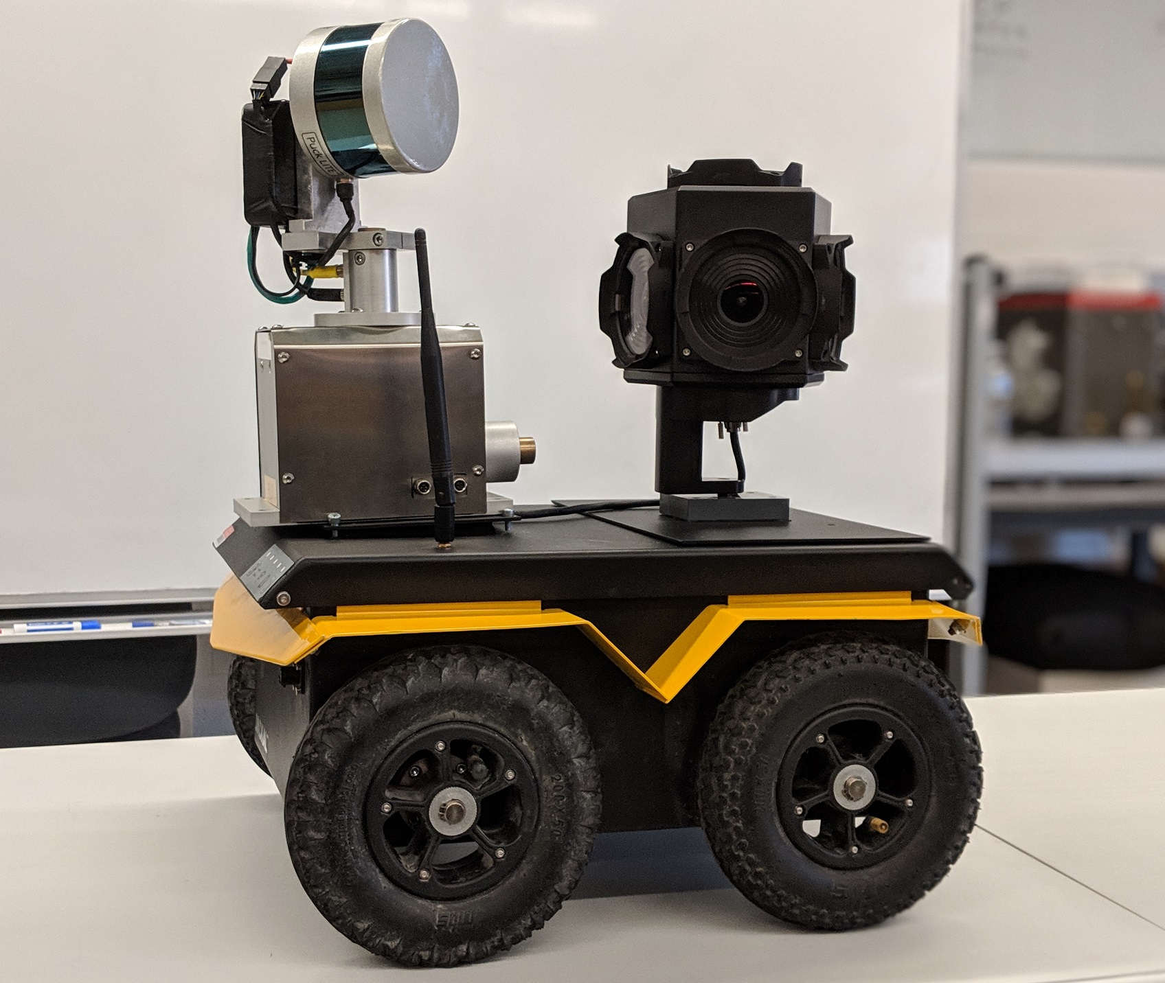
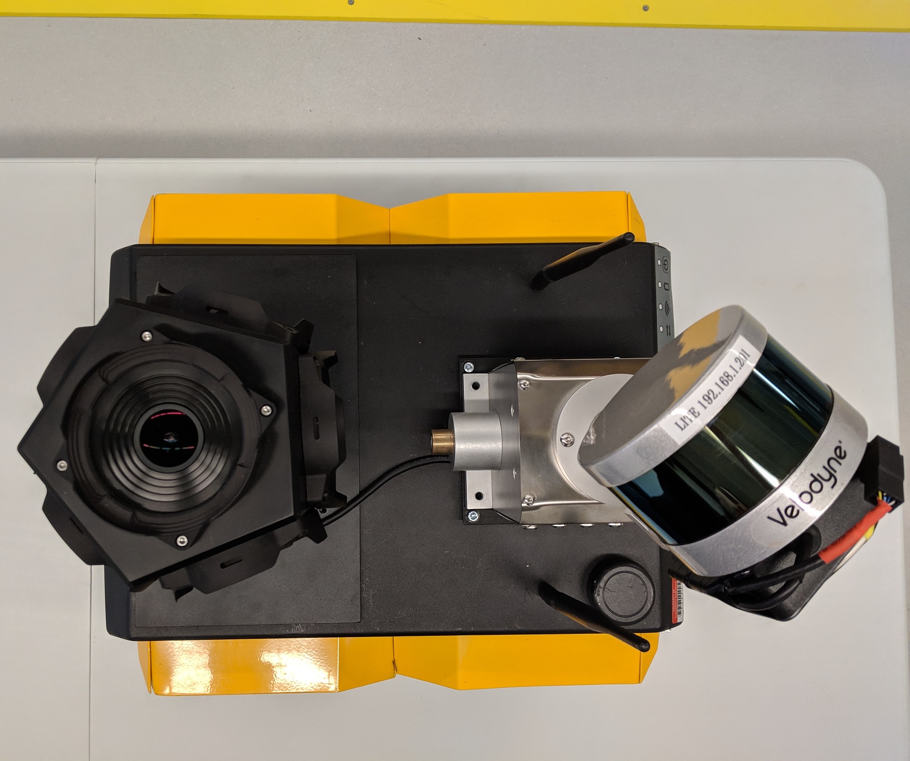
Figure 5 and 6: Jackal based inspection UGV with sensors including (A) Rotating Lidar (VLP-16) (B) Flir Ladybug5+ (C) GPS (D) IMU
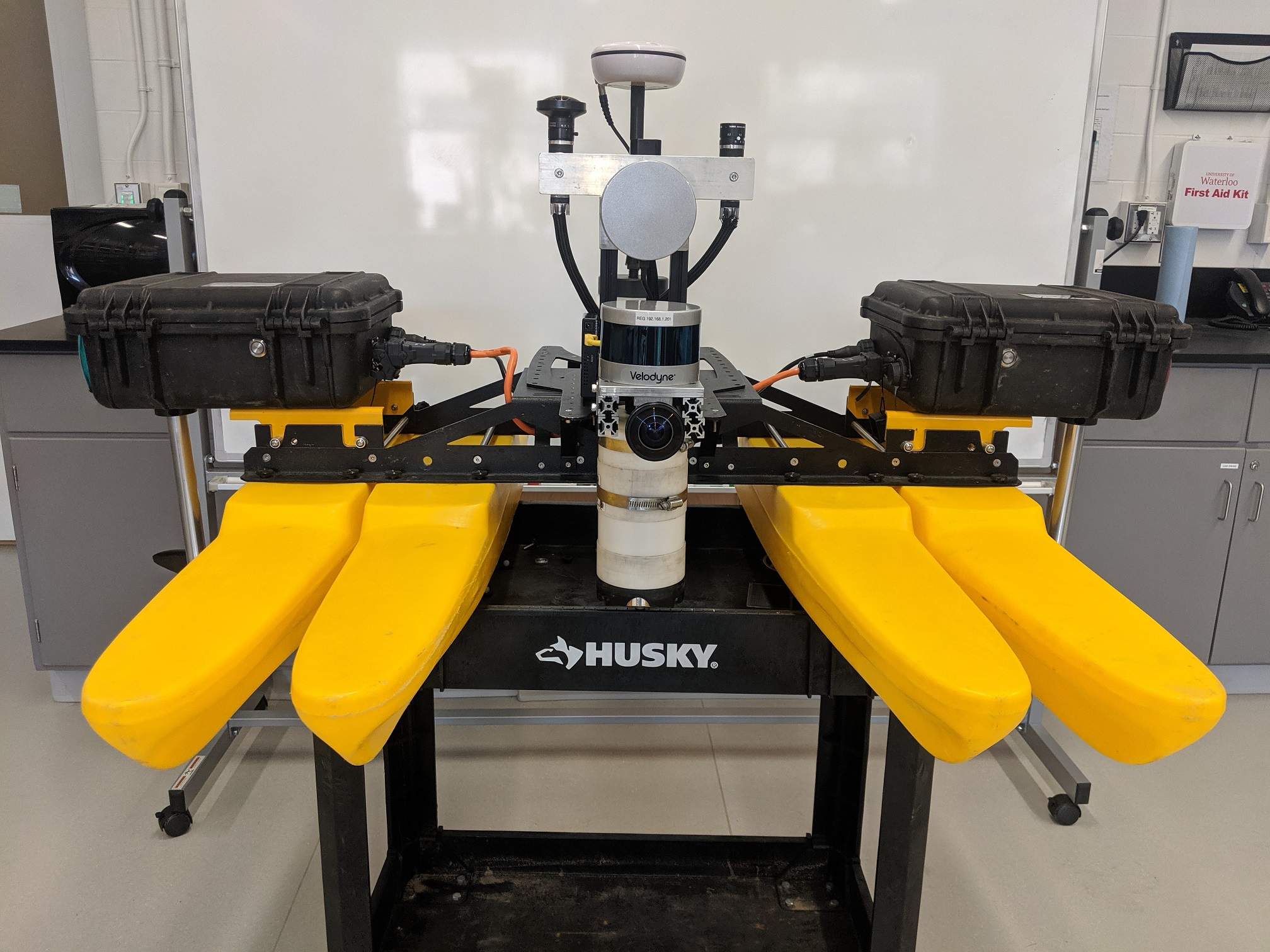
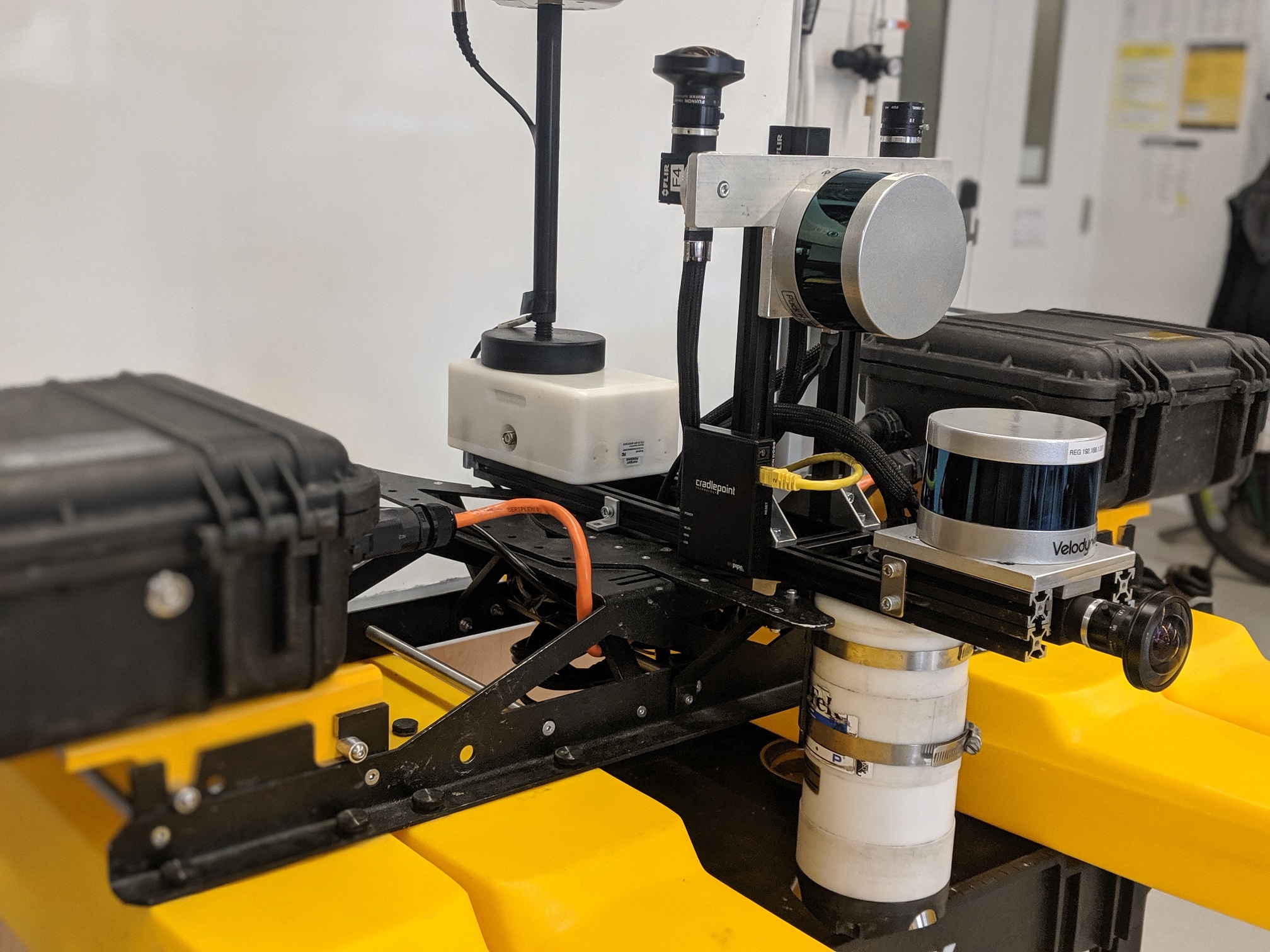
Figure 7 and 8: King Fisher based inspection USV with the same sensor as the Husky UGV, with an additional multi-beam sonar for underwater mapping.
The above robotic platforms are specifically designed for ground/surface based infrastructure inspection. All sensors are time synchronized and calibrated intrinsically for internal parameter estimation, and extrinsically for estimates of the physical transformation between each sensor frame.
The mapping procedure currently works in two separate processes. First, an online SLAM solution is implemented to do real-time, lower quality mapping. This allows the operator to view the map as it is being generated so that they can ensure full coverage of the area of interest. After data collection has completed, the map is automatically refined using a batch optimization approach implemented with GTSAM. Online mapping is currently performed using an EKF, or LOAM (Lidar Odometry and Mapping). We are currently working on a fixed-lag smoother implementation for better online mapping.
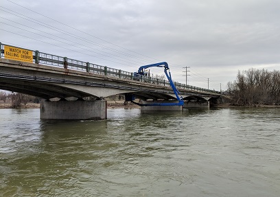
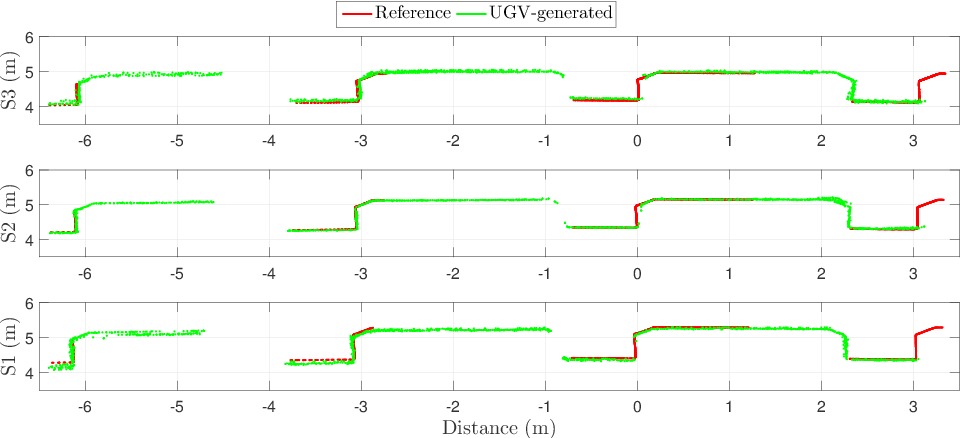
Figure 6 shows the results from the Conestogo Bridge mapping when compared to a baseline scan using a
Faro Focus .
Here, we take cross-sections of the maps generated by our platform (green) and compare to cross sections from the
Faro scanner (Red) at the same locations on the bridge. This illustrates the accuracy capabilities of this preliminary
mapping software.
It should also be noted that the time to generate this map with our platform is on the order of
5 to 10 minutes whereas the time required to scan the same area with the Faro took us approximately two hours.
The core contribution of our work is the extension of 3D mapping to perform automated inspection. To do this, we collect
RGB and IR images that are synchronized with the lidar scans. Based on our pose estimates from SLAM and the extrinsic
calibrations, we can perform image analysis on to detect defect/objects of interest and project that information to the point cloud.
Our point clouds contain not only x,y,z,r,g,b,i (thermal intensity) information, but each point also contains
a probability of the point belonging to a specific class. Classes for bridge inspection for example are:
(i) sound concrete, (ii) crack, (iii) delamination, (iv) spall, and (v) patch. We then group the points belonging
to each class into defect objects in order to calculate and track dimensions of each defect.
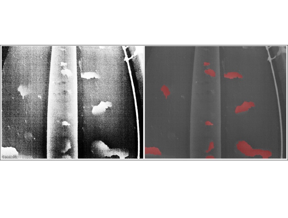
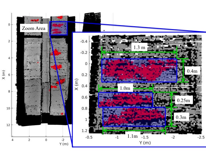
An example use case of this technology was the delamination survey of the Conestogo River Bridge. A delamination is a patch of concrete that has detached from the rest of the structure but has not fallen off. Delaminations introduce air voids which act as insulating layers that alter heat travel through the structure which can be seen in infrared images. In this example, we use image processing tools to detect the delaminations in the infrared images (Fig. 10). The images are labeled on a pixel-wise basis and these "delaminated" pixels are projected onto the point cloud using ray-tracing. Since the point cloud is to-scale, we can then directly measure the size of the defects (Fig. 11).
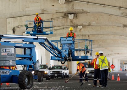
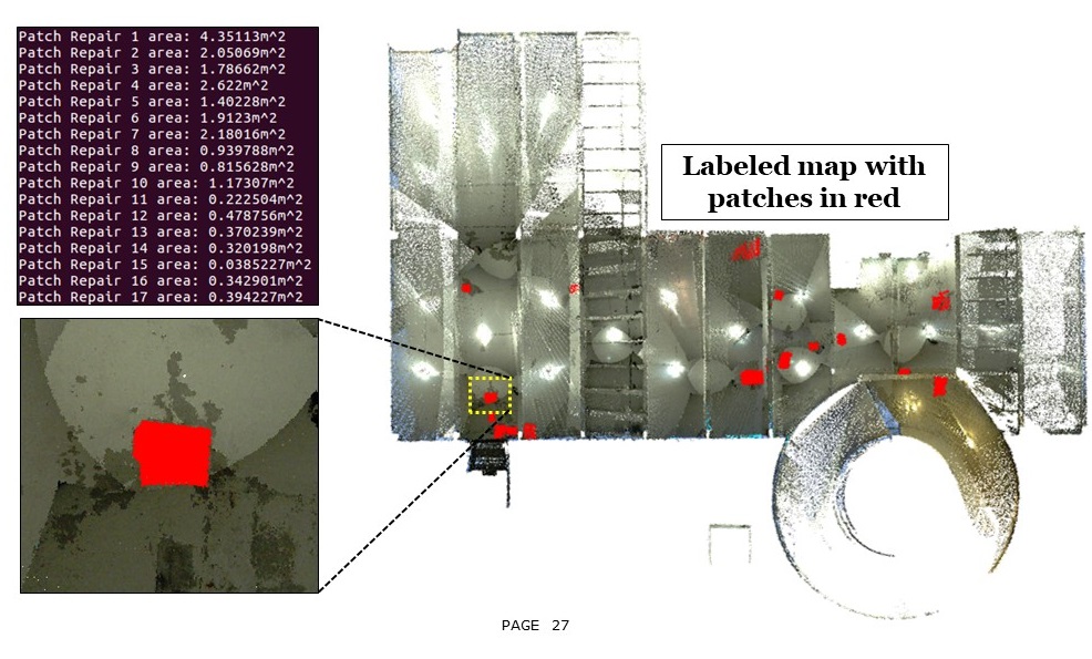
Another example use case for this technology is concrete patch detection and quantification. For this project, we scanned a parking garage in Kitchener, ON. The RGB images from this scan were used to detect concrete patches which were then projected to the point cloud map and coloured in red (Fig. 12). In this case, we also clustered together the points associate with each patch and calculated the area of each patch. We were then able to produce an inspection report with all patches and their size. This whole inspection process was automated (besides the data collection where the robot was driven manually).
Automating data collection for inspection is another area of focus of this work. We have worked on two different GPS waypoint navigation packages in ROS that can be used to automate data collection. Both packages were created in collaboration with Clearpath Robotics.
The first implementation was stictly using open-source ROS packages with minimal custom nodes. The waypoint navigation package was built to work with Clearpath robots having a GPS, IMU, 2D front facing Lidar, and wheel odometry. It allows a user to either input the GPS waypoints, or collect the waypoints with the robot ahead of time. Obstacle avoidance is also fully incorporated into the software. Full tutorials can be found here, and the source code can be found here.
Video demonstrations of this package are shown below. The video on the left shows standard waypoint navigation with obstacle avoidance. The video on the right shows how it can be combined with a mapping kit for autonomous mapping.
Further development was performed with Clearpath Robotics to release a more reliable and user-friendly package. For information on purchasing this package, see Clearpath's website. Video demonstations are shown below.