Geomechanics of Hydraulic Fracturing
- Hydraulic Fracturing is an enabling
technology for Oil and Gas development from tight reservoirs. Geomechanics combines the
disciplines of solid, fluid, rock, poro, and
fracture mechanics. When planning hydraulic fracture operations, numerous
design variables need to be accessed, including well, stage, and cluster spacings,
fluid and proppant injection rates and volumes, and fluid and proppant properties.
Hydraulic Fracturing increases the permeability of a reservoir by deforming
and fracturing the rock mass using a fluid injected under high
pressures and rates and then propping the fractures created using a proppant.
Despite the importance of geomechanics to hydraulic fracturing, current practice is
often based largely upon an expensive trial and error approach. While fields trials will
always be necessary, the application of geomechanics in the planning stages can reduce the
number of costly iterations. This research aims to answer questions
such as:
- How should Re-fracturing operations be performed?
- What is the likelihood of Frac Hits in a particular well?
- How much Production can be expected from a particular stimulation plan?
- How does hydraulic fracturing impact Well-Bore Integrity?
- How should Clusters be oriented and spaced?
- What is the optimal Stage spacing?
- How does the Natural Fracture Network impact stimulation efficiency?
- What will be the role of Stress Shadowing in a particular well?
- This research is conducted in collaboration with Dr. M. Dusseault and Dr. Erfan Savaramini of the University of Waterloo
Carbon Sequestration - Analysis and Uncertainty Assessment
Carbon sequestration, the process by which CO2 emission from large emitting sources is captured and then injected into deep saline aquifer, is seen as a technologically viable means of significantly reducing Green House emissions. In North America, abandoned wells from petroleum extraction are prolific in the same high-porosity, high-permeability sedimentary units that would be used for carbon storage. Because of the high uncertainty in subsurface material properties and structure, simulation models which can be used to accurately quantify CO2 leakage to the surface and/or into fresh water aquifers are in high demand. In this project, we are working to develop new analysis tools to accurately and efficiently model carbon sequestration in multi-aquifer systems. For more information please see our recent articles (FINEL 2010), (AWR 2014) (IJGGC 2014) , (SERRA 2014), and (IJNME 2014) .
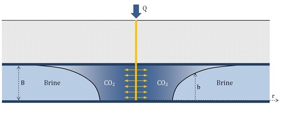
Illustration of the injection of CO2 into a
saline aquifer.
Since carbon sequestration is performed deep underground (greater than 800m), there is a great amount of uncertainty associated with the process. For example, the porosity, permeability, and gap rock fracture pressure are all assessed from limited data sets and interpolation between measurement locations is required. We are working on developing tools to quantify the role of the uncertainty in model inputs on the uncertainty of model outputs. This will allow operators to more deeply understand what additional information needs to be collected to improve predictions for quantities of interests, such as CO2 plume shape. Furthermore, we are developing Bayesian Analysis tools to adaptively update model parameter distributions using the most up to date site monitoring data, so that predictions of future system behaviour are as accurate as possible. For more information please see our recent articles (IJGGC 2014)
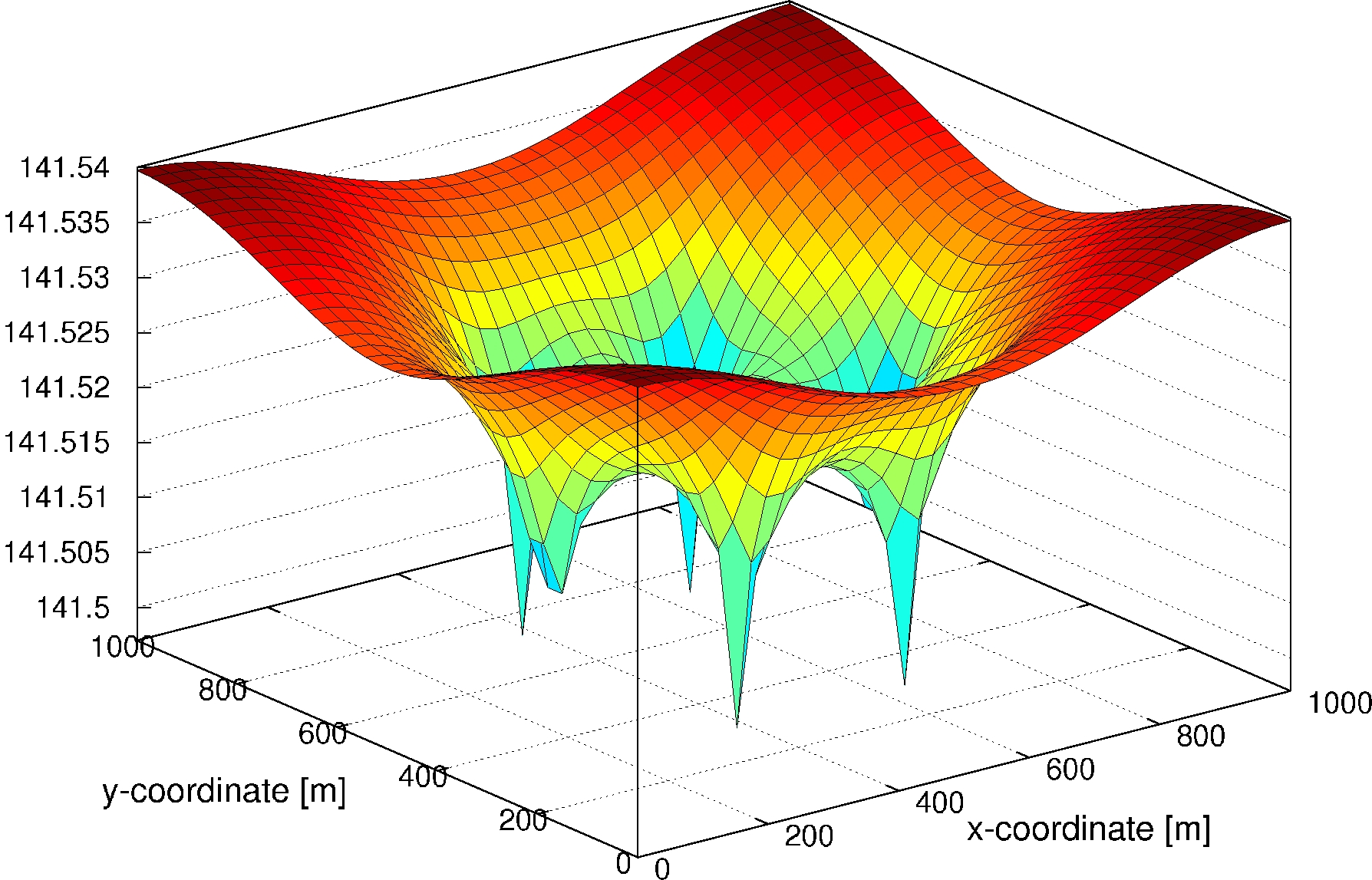
Head in an aquifer perforated by six abandoned
wells and one injection well. The singularity
in the head at the abandoned wells is captured
by an Extended Finite Element Approximation.
Dislocation Modelling with the Extended Finite Element Method
- Development of numerical methods for continuum based models of dislocations.
- Focus on prediction of plasticity and failure in bulk materials, thin films and MEMS devices.
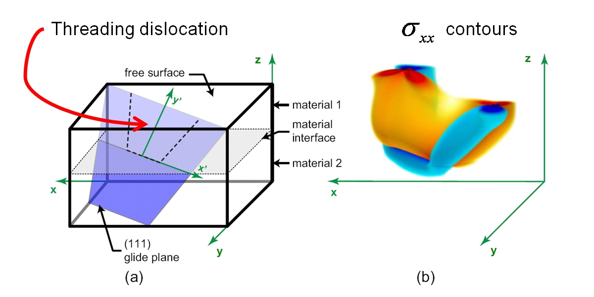
Simulation of a threading dislocation in a SiGe
thin film on an Si substrate. Simulation performed
by
Jay Oswald and published
(doi: 10.1016/j.cma.2008.12.025)
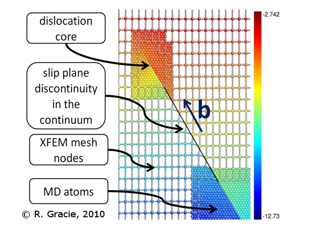
XFEM-BDM: Coupled Continuum and Atomistic Models of Dislocations
Molecular Dynamics (MD) and continuum dislocation models such as Dislocation Dynamics (DD) have been important tools for engineers and material scientists to further the understanding of the macroscale plastic deformation of metals; however, to date these simulations have been largely qualitative. A quantitative understanding of the nature of crystal plasticity from the fundamental level of the nucleation and motion of individual dislocations is a critical step in the design of new materials with tailored strengths and toughness. We have focused our research on the development of numerical methods which couple continuum and atomistic models of materials. This lead to the development of the XFEM-BDM framework for the simulation of cracks and dislocations. In the context of dislocation modelling, the XFEM-BDM allows for atomistic resolution of dislocation core behaviour while still modelling most of the domain with a computationally more efficient continuum model. The XFEM-BDM framework is illustrated below.
Simulation of the propagation of an edge dislocation
using the XFEM-BDM. Displacements in the y-direction
are shown. Results submitted to IJNME. See earlier
XFEM-BDM article
(Gracie and Belytschko, 2009)
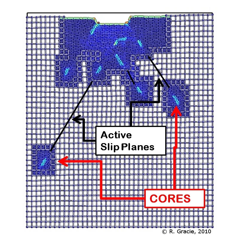
Simulation of a nanoindentation process using
the XFEM-BDM. Atoms are coloured by their energies.
Atoms at the dislocation cores are coloured
light blue. Results submitted to IJNME. See
earlier XFEM-BDM article
(Gracie and Belytschko, 2009)
Modelling Extreme Loads on Pipelines
- Development of soil-structure interaction models for simulating the effect of ice scours on pipelines
- Study of very large soil deformations
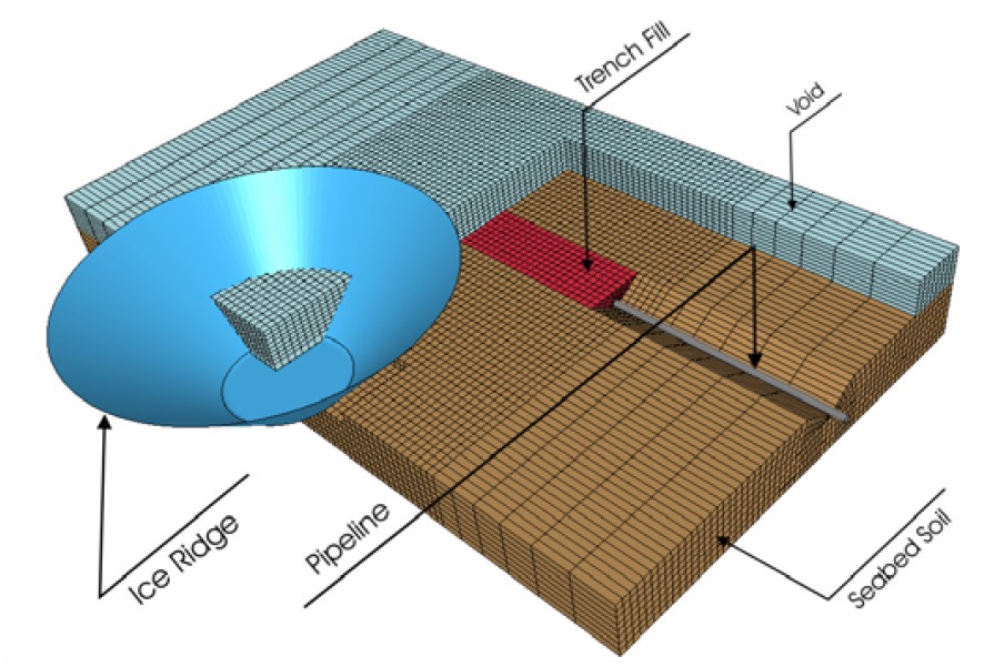
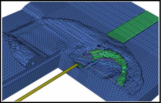
Left: Finite element mesh for an ice scour simulation. Right: Soil deformations due to ice scouring. Green material denotes soil initially in the trench.